| Alarm Display | Alarm Name | Meaning |
| A.020 | Parameter Checksum Error | The data of the parameter in the SERVOPACK is incorrect. |
| A.021 | Parameter Format Error | The data format of the parameter in the SERVOPACK is incorrect. |
| A.022 | System Checksum Error | The data of the parameter in the SERVOPACK is incorrect. |
| A.030 | Main Circuit Detector Error | Detection data for power circuit is incorrect. |
| A.040 | Parameter Setting Error | The parameter setting is outside the allowable setting range. |
| A.041 | Encoder Output Pulse Setting Error | The encoder output resolution setting (Pn281) is outside the allowable setting range or does not satisfy the setting condi tions. |
| A.042 | Parameter Combination Error | Combination of some parameters exceeds the setting range. |
| A.044 | Semi-closed/Fully-closed Loop Control Parameter Setting Error | The settings of the fully-closed option module and Pn00B.3, Pn002.3 do not match. |
| A.04A | Parameter Setting Error 2 | There is an error in settings of parameters reserved by the system. |
| A.050 | Combination Error | The SERVOPACK and the linear servomotor capacities do not match each other. |
| A.051 | Unsupported Device Alarm | The unsupported device unit was connected. |
| A.080 | Linear Scale Pitch Setting Error | The setting of the linear scale pitch (Pn282) has not been changed from the default setting. |
| A.0b0 | Cancelled Servo ON Command Alarm | The Servo ON command was sent from the host controller after the utility function was executed to turn the power to the linear servomotor ON. |
| A.100 | Overcurrent or Heat Sink Overheated | An overcurrent flowed through the IGBT. Heat sink of the SERVOPACK was overheated. |
| A.300 | Regeneration Error | Regenerative circuit or regenerative resistor is faulty. |
| A.320 | Regenerative Overload | Regenerative energy exceeds regenerative resistor capacity. |
| A.330 | Main Circuit Power Supply Wiring Error | • Setting of AC input/DC input is incorrect. • Power supply wiring is incorrect. |
| A.400 | Overvoltage | Main circuit DC voltage is excessively high. |
| A.410 | Undervoltage | Main circuit DC voltage is excessively low. |
| A.450 | Main-Circuit Capacitor Overvoltage | The capacitor of the main circuit has deteriorated or is faulty. |
| A.510 | Overspeed | The linear servomotor speed is over the maximum allowable speed. |
| A.511 | Overspeed of Encoder Output Pulse Rate | The set value of the encoder output resolution (Pn281) exceeds the speed limit. |
| A.520 | Vibration Alarm | Vibration at the motor speed was detected. |
| A.521 | Autotuning Alarm | Vibration was detected while performing tuning-less func tion. |
| A.550 | Maximum Speed Setting Error | The Pn385 setting is greater than the maximum speed. |
| A.710 | Overload: High Load | The linear servomotor was operating for several seconds to several tens of seconds under a force largely exceeding rat ings. |
| A.720 | Overload: Low Load | The linear servomotor was operating continuously under a force largely exceeding ratings. |
| A.730 A.731 | Dynamic Brake Overload | When the dynamic brake was exceeded the capacity of dynamic brake resistor. applied, moving energy |
| A.740 | Overload of Surge Current Limit Resistor | The main circuit power was frequently turned ON and OFF. |
| A.7A0 | Heat Sink Overheated | The temperature of the SERVOPACK heat sink exceeded 100°C. |
| A.7AB | Built-in Fan in SERVOPACK Stopped | The fan inside the SERVOPACK stopped. |
| A.820 | Encoder Checksum Error | The checksum results of linear scale memory is incorrect. |
| A.840 | Encoder Data Error | Data in the linear scale is incorrect. |
| A.850 | Encoder Overspeed | The linear scale was operating at high speed when the power was turned ON. |
| A.860 | Encoder Overheated | The internal temperature of linear scale is too high. |
| A.861 | Motor Overheated | The internal temperature of motor is too high. |
| A.890 | Encoder Scale Error | A linear scale fault occurred. |
| A.891 | Encoder Module Error | Linear scale is faulty. |
| A.b31 | Current Detection Error1 (Phase-U) | The current detection circuit for phase-U is faulty. |
| A.b32 | Current Detection Error 2 (Phase-V) | The current detection circuit for phase-V is faulty. |
| A.b33 | Current Detection Error 3 (Current detector) | The detection circuit for the current is faulty. |
| A.bF0 | System Alarm 0 | “Internal program error 0″ occurred in the SERVOPACK. |
| A.bF1 | System Alarm 1 | “Internal program error 1″ occurred in the SERVOPACK. |
| A.bF2 | System Alarm 2 | “Internal program error 2″ occurred in the SERVOPACK. |
| A.bF3 | System Alarm 3 | “Internal program error 3″ occurred in the SERVOPACK. |
| A.bF4 | System Alarm 4 | “Internal program error 4″ occurred in the SERVOPACK. |
| A.C10 | Servo Overrun Detected | The linear servomotor ran out of control. |
| A.C20 | Phase Detection Error | The detection of the phase is incorrect. |
| A.C21 | Hall Sensor Error | The hall sensor is faulty. |
| A.C22 | Phase Information Disagreement | The phase information does not match. |
| A.C50 | Polarity Detection Error | The polarity detection failed. |
| A.C51 | Overtravel Detection at Polarity Detection | The overtravel signal was detected at polarity detection. |
| A.C52 | Polarity Detection Uncompleted | The linear servomotor was turned ON under the condition of polarity detection uncompleted. |
| A.C53 | Out of Range for Polarity Detection | The movement distance exceeded the set value of Pn48E during polarity detection. |
| A.C54 | Polarity Detection Error 2 | The polarity detection failed. |
| A.C80 | Absolute Encoder Clear Error | The data of the absolute linear scale was not properly cleared or set. |
| A.C90 | Encoder Communications Error | Communications between the SERVOPACK and the linear scale is not possible. |
| A.C91 | Encoder Communications Position Data Error | A linear scale position data calculation error occurred. |
| A.C92 | Encoder Communications Timer Error | An error occurs in the communications timer between the linear scale and the SERVOPACK. |
| A.CA0 | Encoder Parameter Error | Linear scale parameters are faulty. |
| A.Cb0 | Encoder Echoback Error | Contents of communications with linear scale is incorrect. |
| A.CF1 | Feedback Option Module Communications Error (Reception error) | Reception from the feedback option module is faulty. |
| A.CF2 | Feedback Option Module Communications Error (Timer stop) | Timer for communications with the feedback option module is faulty. |
| A.d00 | Position Error Pulse Overflow | Position error pulses exceeded the value set for parameter (Pn520) (Excessive Position Error Alarm Level). |
| A.d01 | Position Error Pulse Overflow Alarm at Servo ON | Position error pulses accumulated too much. |
| A.d02 | Position Error Pulse Overflow Alarm by Speed Limit at Servo ON | After a position error pulse has been input, Pn584 limits the speed if the servo ON command is received. If Pn584 limits the speed in such a state, this alarm occurs when the position references are input and the number of position error pulses exceeds the value set for parameter Pn520 (Excessive Posi tion Error Alarm Level). |
| A.d30 | Position Data Overflow | The position feedback data exceeded ±1879048192. |
| A.E00 | Command Option Module IF Initialization Timeout Error | Communications initialization failed between the SERVO PACK and the command option module. |
| A.E02 | Command Option Module IF Synchronization Error 1 | A synchronization error occurred between the SERVOPACK and the command option module. |
| A.E03 | Command Option Module IF Communications Data Error | An error occurred in the data of communications between the SERVOPACK and the command option module. |
| A.E40 | Command Option Module IF Communications Setting Error | An error occurred in establishing communications (settings) between the SERVOPACK and the command option mod ule. |
| A.E50 | Command Option Module IF Synchronization Error 2 | A error occurred in synchronization between the SERVO PACK and the command option module. |
| A.E51 | Command Option Module IF Synchronization Establishment Error | A error occurred in establishing communications between the SERVOPACK and the command option module. |
| A.E60 | Command Option Module IF Data Communications Error | A error occurred in communications between the SERVO PACK and the command option module. |
| A.E61 | Command Option Module IF Synchronization Error 3 | There was a change in timing of synchronization between the SERVOPACK and the command option module. |
| A.E70 | Command Option Module Detection Failure | Detection of the command option module failed. |
| A.E71 | Safety Option Module Detection Failure | Detection of the safety option module failed. |
| A.E72 | Feedback Option Module Detection Failure | Detection of the feedback option module failed. |
| A.E73 | Unsupported Command Option Module | An unsupported command option module was connected. |
| A.E74 | Unsupported Safety Option Module | An unsupported safety option module was connected. |
| A.E75 | Unsupported Feedback Option Module | An unsupported feedback option module was connected. |
| A.E80 | Command Option Module Unmatched Error | The command option module was replaced with a different model. |
| A.EA2 | DRV Alarm 2 (SERVOPACK WDC error) | A DRV 0 error of the SERVOPACK occurred. |
| A.Eb1 | Safety Device Signal Input Timing Error | There is an error in the timing of the safety function input signal. |
| A.ED1 | Command Option Module IF Command Timeout Error | Processing of reference from the command option module was not completed. |
| A.F10 | Main Circuit Cable Open Phase | With the main power supply ON, voltage was low for more than 1 second in phase-R, -S or -T. |
| A.F50 | Servomotor Main Circuit Cable Disconnection | The servomotor did not operate or power was not supplied to the servomotor even though the servo ON command was input when the servomotor was ready to receive it. |
| CPF00 | Digital Operator Transmission Error 1 | Digital operator (JUSP-OP05A) fails to communicate with the SERVOPACK (e.g., CPU error). |
| CPF01 | Digital Operator Transmission Error 2 | – |
| A.- – | Not an error | Normal operation status |
Tin tức
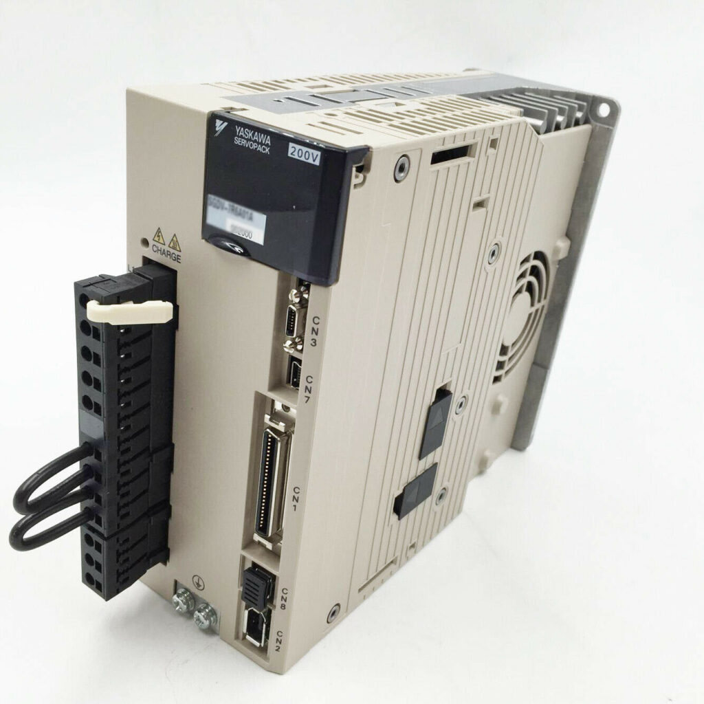
CÁC LỖI THƯỜNG GẶP Ở SERVO YASKAWA SIGMA 5
08
Th6
Th6
Dưới đây là các lỗi thường xuất hiện trên Driver và ý nghĩa của chúng.